Full-Stack Autonomous Driving Research Platform: Hardware-Software Co-Design & Real-Vehicle Verification
TL;DR Passenger-vehicle and four-wheel independent-steering AGV platforms integrate perception, localization, planning, and control for low-speed autonomous driving research.

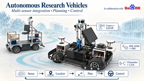 Self-built dual autonomous driving research vehicle platforms: unifying full-suite sensors, edge compute, and drive-by-wire chassis into an integrated full-stack architecture.
Autonomous driving research requires validation beyond idealized simulator environments to directly address real-world ground friction, physical sensor noise, bus communication latency, and actuator non-linearities. In 2019, commercial autonomous testbeds were prohibitively expensive and strictly closed-source, precluding in-depth research into chassis dynamics and custom low-level sensor drivers. To establish an accessible, controllable physical research platform, we undertook the ground-up hardware and software construction of an autonomous driving research testbed.
Between 2019 and 2022, we designed and built two complementary research vehicles: a low-speed pure-electric passenger vehicle configured for campus road cruising, and an omnidirectional research AGV featuring 4-wheel independent driving and 4-wheel independent steering (4WID-4WIS). The engineering effort spanned mechanical mounting fabrication, high/low-voltage isolated power distribution, reverse engineering of proprietary CAN bus protocols, development of Linux SocketCAN drivers, microsecond-level hardware time synchronization across heterogeneous sensors, and a full-stack ROS-based software autonomy suite encompassing perception, SLAM, planning, and control. The platform successfully completed closed-loop verification across diverse representative operational scenarios under realistic campus road traffic.
Project context
Autonomous Driving Research Core · Ground-Up Hardware/Software R&D
To evaluate autonomous driving algorithms on physical hardware rather than purely in simulation, we built full-stack research vehicle platforms from the ground up. Covering chassis adaptation, power distribution, SocketCAN drivers, and ROS autonomy modules, the platform provided an experimental testbed for ongoing laboratory research.
- Platform Deliverables & Multi-Scenario Real-Vehicle Demonstrations
- Two operational drive-by-wire autonomous research platforms; 300+ hours of road testing, 8 real-vehicle closed-loop demonstrations (<5 cm lateral tracking error, <60 ms AEB braking response), and a complete custom ROS autonomy stack.
My contributions
As project lead, built two generations of drive-by-wire autonomous vehicle research platforms (passenger cart and 4WIS AGV) from scratch, accumulating 300+ hours of physical road testing; responsible for drive-by-wire modification, power isolation, CAN bus reverse engineering, and multi-scenario closed-loop validation.
Two Complementary Research Chassis
To comprehensively ground our research across disparate operational domains, we developed two distinct physical platforms:
Low-Speed Campus Research Cart: Configured with passenger-carrying seating, a standard automotive steering column, and hydraulic braking. Its open frame and high payload capacity accommodate heavy sensor payloads: a 32-beam spinning 3D LiDAR, forward stereo and surround wide-angle cameras, dual-antenna RTK-GNSS, a high-rate IMU, and a ruggedized industrial PC equipped with high-performance discrete GPUs. This vehicle serves as the primary testbed for large-scale metric-topological SLAM, multi-modal perception, traffic interaction, and cooperative V2X platooning.
Compact 4-Wheel Independent Drive & Steer (4WID-4WIS) AGV: Equipped with eight independent brushless DC servomotors (four driving wheels, four steering hubs). Bypassing the non-holonomic kinematic limits of traditional Ackermann steering, the vehicle dynamically reconfigures its steering mode in software: standard front-wheel Ackermann, diagonal crab-steering, pure lateral translation, and zero-radius pivot spinning around its chassis center. This platform provides an agile testbed for high-speed obstacle avoidance maneuvers and extreme tight-space parking.
Both vehicles enforce a foundational design paradigm: exposing algorithms directly to real-world tire-ground compliance, CAN transmission jitter, and actuator deadbands, thereby establishing a physical benchmark for subsequent algorithmic robustness.
Multi-Sensor Fusion → State Estimation → Planning → Drive-by-Wire Actuation
Full-stack onboard ROS autonomy connects perception, SLAM, and planning; the drive-by-wire chassis executes closed-loop control over CAN.
Ground-Up Electrical & Sensor Topology
Without commercial turnkey kits, integrating disparate sensors and actuators into a fail-safe vehicular platform required overcoming fundamental electrical isolation, extrinsic calibration, and temporal synchronization challenges.
Scroll horizontally to view the remaining columns.
| Subsystem | Configuration & Role | Core Engineering Challenges Overcome |
|---|---|---|
| Drive-by-Wire & CAN Bus | Electronic steering motor, throttle potentiometer, and hydraulic brake booster | Reverse-engineered proprietary cyclic DBC protocols; built 100 Hz deterministic Linux SocketCAN drivers with heartbeat fail-safe routines |
| 3D LiDAR | 32-beam / 16-beam mechanical spinning LiDAR for 3D mapping and obstacle ranging | Custom CNC aluminum vibration dampers isolating chassis road shock; calibrated beam reflectivity intensity decay curves |
| HDR Industrial Cameras | Narrow-FOV (60°) and wide-angle (120°) cameras for lane segmentation and object vision | Mitigated severe lens flare transitioning into shaded tree canopies; designed rigid camera-LiDAR multi-modal calibration targets |
| RTK-GNSS Differential GPS | Dual-antenna receiver delivering centimeter-level 3D coordinates and true heading | Optimized 1.5 m baseline antenna placement; mitigated carrier-phase slip and multipath jumps beside dense concrete campus structures |
| Automotive IMU | 6-axis tactical-grade inertial unit providing 200 Hz linear acceleration and yaw rates | Mechanically aligned IMU sensing center with chassis rear-axle centerline; performed online thermal bias drift calibration |
| Ultrasonic Transceiver Array | 8 bumper-mounted ultrasonic sensors for near-field blind-spot guarding (0.2–2.5 m) | Optimized acoustic beam-cone overlap geometry, enforcing sequential time-multiplexed firing to eliminate cross-talk |
| Power Distribution & Isolation | 48V traction battery pack converted to isolated 12V/24V clean bus | Custom electrical distribution enclosure with TVS diodes and optocouplers, suppressing motor back-EMF voltage surges and ground loops |
1. Hardware Hard-Triggering & Microsecond Temporal Synchronization
At vehicle speeds of 25 km/h, a 100 ms timing desynchronization between sensors induces an spatial projection error approaching 0.7 meters. Relying on software system timestamps (ROS Time) introduces non-deterministic OS scheduling jitter incompatible with feature-level sensor fusion.
We engineered a multi-tier hardware synchronization architecture:
- PTP and PPS Nanosecond Clock Locking: The RTK-GNSS receiver, upon locking satellite constellations, generates a precision Pulse Per Second (PPS) square wave and GPRMC NMEA timing packets. The 32-beam LiDAR ingests the PPS signal, synchronizing its internal clock to absolute UTC time within nanoseconds;
- FPGA/Microcontroller External Optical Exposure Triggering: A dedicated microcontroller captures the PPS pulse and synthesizes a phase-locked 20 Hz square wave sent to the external trigger pins of industrial cameras. This forces camera sensor exposure to coincide exactly with the moment the LiDAR spinning beam sweeps through the forward field of view;
- Driver nodes read hardware frame timestamps directly from peripheral registers, compressing inter-sensor temporal alignment error below 1 millisecond.
2. Rigid Extrinsic Joint Calibration (LiDAR-Camera-IMU)
To eliminate spatial misalignments:
- The rigid transformation between the camera optical center and LiDAR coordinate frame is optimized using a custom calibration board featuring hollow circular cutouts, simultaneously minimizing 3D laser point-to-plane fitting errors and 2D visual circular re-projection errors;
- IMU-to-LiDAR spatial extrinsics are identified through continuous sinusoidal steering maneuvers and rapid acceleration profiles in open areas, parameterizing trajectories via continuous B-splines to minimize angular velocity and linear acceleration residuals, reaching millimeter and 0.1-degree alignment accuracy.
3. Proprietary CAN Bus Reverse Engineering & Deterministic SocketCAN Drivers
With native chassis controller (VCU) documentation withheld, we captured raw bus traffic using CAN analyzers during manual driving. By correlating driver throttle inputs, pedal pressure, steering wheel sweeps, and wheel encoder pulses, we systematically isolated and mapped the cyclic DBC communication matrix.
We subsequently built an industrial-grade Linux SocketCAN driver:
- Implemented a 100 Hz deterministic periodic thread transmitting steering angle, throttle voltage, and brake pressure setpoints;
- Integrated a dual-directional watchdog supervisor: if the VCU misses valid heartbeat packets for $>100\text{ ms}$, onboard firmware immediately disengages autonomous drive and engages gentle mechanical braking, preventing runaway faults caused by upstream software crashes.
Full-Stack ROS Autonomy Architecture
The software stack operates on Ubuntu Linux and ROS with optimized shared-memory IPC, partitioned into three core decoupled pipelines:
1. Localization & High-Precision Mapping Pipeline
- Tightly Coupled LiDAR-Inertial SLAM: Extracting geometric edge and planar features from raw 32-beam point clouds, the frontend fuses high-rate IMU pre-integration priors within a factor graph optimization backend. Between keyframes, relative motion increments and bias updates are factored alongside LiDAR point-to-plane geometric residuals into an incremental smoothing and mapping (iSAM2) factor graph, rendering globally consistent 3D point-cloud maps of campus roadways;
- 50 Hz Online NDT Localization: Within the pre-built metric voxel map, incoming point clouds are registered using the Normal Distributions Transform (NDT) at 50 Hz. Each spatial voxel approximates local point distributions via 3D Gaussians. Even when traversing covered pedestrian corridors and dense underpasses where GNSS signals vanish, NDT scan registration maintains continuous state estimation without trajectory drift or discrete position jumps;
- Dual-Antenna Differential Kinematic Heading: Fixed dual antennas establish an instantaneous physical baseline across the vehicle roof, determining true vehicular heading even at zero velocity without dead-reckoning integration drift.
2. Environmental Perception & Scene Understanding Pipeline
- Bird’s-Eye-View Visual Lane Tracking: Monocular camera images undergo distortion rectification and Inverse Perspective Mapping (IPM). A lightweight segmentation network extracts lane boundary pixels, fitting polynomial curves to output continuous road curvature and lateral offset for steering regulation;
- Multimodal 3D Object Detection & Tracking: 2D deep learning detectors classify pedestrians, bicycles, and vehicles in image space. Detected bounding frustums are back-projected into spatial point clouds to segment candidate point clusters and fit 3D oriented bounding boxes. An Interacting Multiple Model Unscented Kalman Filter (IMM-UKF) bridges constant-velocity and constant-turn-rate motion hypotheses to publish stable obstacle velocity vectors.
3. Hierarchical Planning & High-Rate Actuation
- Hierarchical Decision State Machine: Finite state machines (FSM) govern macroscopic mission transitions across cruise, dynamic yield, intersection negotiation, bay parking, and emergency stop. Local trajectory generators sample candidate polynomial trajectories in the Frenet frame to dodge static obstacles and slow pedestrians;
- Dual-Loop Dynamic Tracking Control: Lateral control combines Pure Pursuit lookahead with Linear Time-Varying Model Predictive Control (LTV-MPC) over a dynamic bicycle model, enforcing steering angle limits and tire lateral slip angle saturation bounds to eliminate overshoot during high-curvature turns. Longitudinal control employs closed-loop PID with speed feedforward, transmitting steering and braking commands at 100 Hz over CAN.
Seven Real-Vehicle Closed-Loop Scenarios
The seven video recordings document extensive field testing across campus thoroughfares:
- Real-Time 3D LiDAR Mapping: The passenger vehicle cruises smoothly under dense tree canopies, incrementally rendering metric 3D point-cloud geometry of building facades and road curbstones;
- High-Precision SLAM Waypoint Following: Operating with GNSS antennas disconnected, the vehicle navigates autonomously through long, winding campus avenues guided solely by real-time NDT point-cloud matching;
- Vision Lane Centering on 4WIS AGV: The forward camera parses faded white road lines, while the 4WIS chassis dynamically modulates steer angles to remain centered in the travel lane;
- Dynamic Roadside Object Tracking: Onboard detectors identify pedestrians crossing intersections and oncoming bicycles, maintaining 3D bounding boxes and trajectory predictions;
- Autonomous Emergency Braking (AEB) Verification: When an obstacle mannequin is rapidly thrust into the vehicle path, perception computes Time-to-Collision ($\text{TTC} < 1.2\text{s}$) within 60 ms, triggering full hydraulic clamp lockup to halt the vehicle 0.8 meters before the target;
- Precision Bay Parking: Ultrasonic sensors measure bay clearance, allowing the planner to execute a two-stage reverse trajectory that parks the 4WIS AGV neatly aligned with painted stall markers;
- V2X Connected Platooning: Over 5.8 GHz ad-hoc wireless mesh links, lead-vehicle acceleration and braking intentions are shared at 100 Hz, enabling two autonomous vehicles to maintain tight, zero-lag platoon spacing through multi-turn courses.
Engineering Summary & Technical Takeaways
Building two complete physical autonomous platforms from bare metal established foundational systems engineering insights:
- Physical Ground Truth Governs Algorithmic Success: Simulators hide bus dropouts, high-frequency frame vibration, electrical ground loops, and motor deadbands. Only by directly debugging power distribution surges and actuator dead zones on real iron can one design resilient control architectures with adequate feedforward and fail-safe watchdogs.
- Deterministic Timing Underpins Sensor Fusion: Sophisticated geometric algorithms fail if multi-modal sensor streams suffer millisecond-scale timestamp jitter. Enforcing hardware-level PPS clock discipline and external exposure triggering is a prerequisite for reliable real-world perception.
- Reusable Modular System Foundation: The full-stack hardware-software architecture established in this project provided directly transferable foundational modules for subsequent laboratory research and industry partnerships in mobile robotics and autonomous valet parking.
- Hardware-Level Heartbeat Watchdogs as Safety Primitives: Upstream Linux software stacks inevitably experience occasional thread freezes, driver crashes, or kernel scheduling delays. Guaranteeing that the low-level chassis microcontroller automatically cuts throttle and engages gradual hydraulic braking when cyclic CAN heartbeats drop for 100 ms is what keeps physical autonomous prototypes safe during high-speed live road trials.